
Please note: this paper is available for download on our PDF downloads page as well.
Michel Brassard, Contour Dynamics Inspection Systems, Levis, Qébec, G6V 7M5, Canada and Techno Diffusion NDT Systems, Montreal, Canada
Deborah Hopkins, BERCLI Corp., Berkeley, CA 94703
JeanÂâ€Noël Noiret, EADS Composites Aquitaine, Salaunes, 33160, France
Abstract: Achieving high-speed inspection rates for complex composite parts requires versatile and integrated systems that meet the challenges of automated part handling and NDT for ship sets that can include hundreds of different parts. Cost-effective integrated solutions are presented that are being successfully used to inspect composite parts for fully automated aerospace applications. The most appropriate solution for a given ship set depends on factors that include detection and sizing requirements, the range of sizes and geometries of the parts, the required inspection speed and cost constraints. The challenges of optimizing different technologies and integrating them into a single system are described for a recently implemented industrial solution. Lessons learned from the project are presented both in terms of technology integration and implementation of a new ultrasonic software algorithm. Surface-Adaptive Ultrasound (SAUL) is a very recent advancement in phased-array technology that is being used to overcome inspection challenges that include highly contoured surfaces; parts with small radii such as those often found on blades and stiffeners; rough and irregular surfaces including regions of ply dropoff and lap joints; and parts with varying shape, curvature, and thickness with length. Although vision systems and robots can be used to achieve highly accurate part following, the part-to-part variability that is typically encountered with composites creates problems for automated part and probe positioning, as well as accurate part tracking. This paper demonstrates the performance of a cost-effective inspection solution for complex-geometry composites in a high-volume production environment achieved by combining advanced UT technology with industrial robotics and vision technologies.
Introduction
Aerospace composite manufacturers face the reality that traditional inspection approaches are inefficient for the new generation of composite parts. The integration of NDE into the manufacturing process is a potential solution to this problem. Although the ultrasonic inspection of complex parts using Computer-Aided-Design (CAD) drawings and Teach-and-Learn methods is frequently used in automated NDT of aerospace components, it is uncommon for these systems to be required to rapidly inspect a large number of part types with various geometries. An added difficulty frequently encountered with composites, is that actual part geometries differ slightly from CAD drawings. In today’s competitive environment, NDT must become part of the design and manufacturing process to meet requirements for throughput and efficiency. The time required to go from CAD drawings (which for aerospace purposes are often in the form of CATIA drawings) to inspection must be reduced. Importation of CAD drawings into NDT systems or teach-and-learn processes is not sufficient to deal with the increased use of CAD data with greater geometric part complexities. In the same way that manufacturing was integrated with CAD/CAM systems some years ago, the next generation of inspection systems must be fully integrated into the manufacturing process to meet current production challenges.
Implementation of Processes
Fully integrated Computer-Aided Design and Manufacturing Systems are referred to as CAD/CAM. CAD involves creating computer models defined by geometrical parameters. Computer-Aided Manufacturing (CAM) uses geometrical-design data to control automated machinery. CAM systems are associated with computer numerical control (CNC). Modern CAD/CAM systems differ from older forms of numerical control (NC) in that geometrical data no longer has to be encoded mechanically. The analogy to current automated NDT systems is evident; we are commonly still encoding our systems in isolation without interaction with other departments. The system described in this paper is a CAD/CANDT system in which design processes and non-destructive testing are embedded. Making the analogy to CAM systems, NDT is fully
integrated and human intervention is not required before or during the inspection. Implementation of a CAD/CANDT system offers a number of benefits including a reduction in the time required to design scan plans for new parts in addition to a reduced cycle time. Other integration objectives are sharing information, avoiding duplication of work, reducing wasted effort, eliminating non-value activities, and standardizing software suites, which as a consequence frees up valuable NDT resources to perform NDT evaluations. The processes required to perform an inspection are schematically shown in Figure 1. These processes are no different than what is done for a part to be machined.
 The first step is to import a CAD/CATIA drawing into the path-generating software (Mastercam) to create a tool path or from an NDT perspective, a scan plan. The scan plan is converted into CNC codes to inspect the part. Conversion is done using a post processor that translates toolpath data from Mastercam into CNC codes that a controller such as the Siemens SInumerik can interpret (ISO-programming codes or G codes). These codes are what the operator sees when the machine is inspecting. ISO codes include instructions on where to move, how fast to move, and what path to follow. In essence, the system becomes a machine tool. We therefore
embrace machining technology without performing manufacturing.
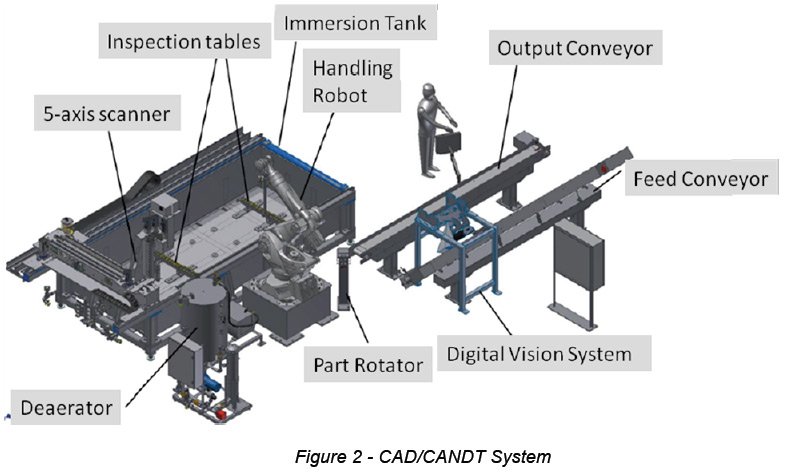
For example, Figure 2 shows a practical implementation of a system that is using the above technology to automatically plan, load, inspect and unload composite parts. This is what is loosely called a CAD/CANDT system.
Integration Challenges
Integrating multiple technologies into a single system is a complex and challenging operation. Learning how to make effective use of existing CAD/CAM technologies and adapting them to NDT requires some planning, as processes are different. A machining program, by definition, does everything from the front surface. However, in NDT we must control what goes inside the material. For example, when inspecting a radius the coverage of the back surface is quite different than what is seen from the front surface. We must therefore take into consideration the ultrasonic physical phenomena when planning our scan plan. The challenges that we face
include:
I. Limited familiarity with multiple disciplines. CAD/CAM technicians and engineers are not usually proficient in NDT. Similarly, NDT personnel are not typically familiar with CAD intricacies. This is a major stumbling block in technology integration. It can be difficult to Integration of Robotics & SAUL for Automated Inspection of Composite Parts NDT of Composites Seattle WA – 13-14 May 2013 Page 4 exchange information and communicate when each party does not understand the other party’s field of competence.
II. Software. NDT is a niche sector, and not the primary market for standard CAD/CAM software packages. Although these packages typically have inspection tools, they were not part of the developer’s original focus, making NDT customization more difficult. It is, however, still doable.
III. Time. To successfully incorporate beneficial technology requires an investment of time up front during pre-production planning. The payoff is that the NDT system cycle is much faster because the machine utilization is fully dedicated to inspection.
IV. Training. NDT personnel are inexperienced in the use of machine codes. In the same way that machinists have learned to interpret and use these tools to their benefit, NDT personnel must be trained to use these tools effectively for inspection. CAD/CANDT has the potential to eliminate some of the inefficiencies that arise from the way NDT is currently being implemented into production. Some questions we in the NDT community must ask ourselves:
- Is NDT being considered as part the design process to facilitate inspectability?
- Is the inspection machine time used efficiently?
- Why is it that the tool paths for machining are done by the CAM office whereas inspection tool paths (scan plans) are done by NDT personnel?
- Why are we using the inspection system to simulate inspection rather than using commercially available software commonly used for machine tools?
Functionally, for integration we need to look closely at the points of failures/weaknesses of the system. Technologies can work together, to the benefit of all, if CAD, CAM and NDT personnel are working in closer cooperation. To perform effectively, a manufacturer needs its teams to operate as a unified group; working towards common business goals, sharing information about the tools that are used. NDT cannot and should not operate in isolation.
Ultrasonic Inspection
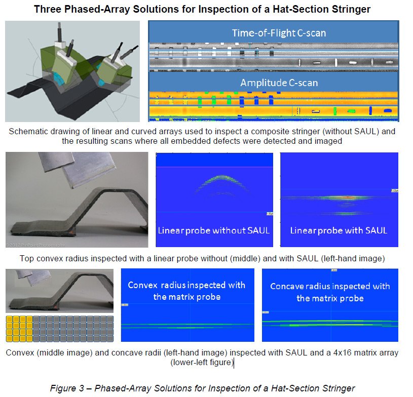
Composite parts inspected using the immersion system represented in Figure 2 have complex 3D shapes and include tight radii. Inspection of these parts using a conventional phased-array approach requires a combination of curved and flat probes. The approach is illustrated in the top row of Figure 3 for a hat-section stringer where linear and curved arrays have been optimized for each radius and the flat sections (as shown in the schematic diagram). Accurate positioning
of the curved arrays is essential for obtaining accurate results, and this can be particularly difficult on long composite parts. When accurate positioning is maintained, very good results can be obtained. The time-of-flight and amplitude C-scans shown on the right are from a hatsection test specimen with known defects, all of which were successfully detected and imaged using the probes illustrated in the schematic drawing. The middle row of Figure 2 shows Bscans for the top convex radius obtained for an actual composite stringer using a linear probe (as illustrated in the left-hand photograph). B-scans were obtained with the linear array without SAUL (middle image) and with SAUL (right-hand image). Applying the surface-adaptive SAUL algorithm (described later in the paper) allows a backwall signal to be measured, but the lateral extent over which there is a strong backwall signal is relatively short. The uniformity of measured signals and the lateral extent of the backwall signal are greatly improved using a 4×16 matrix array optimized for use on aerospace composites (a schematic drawing of the matrix probe is shown in the bottom-left corner of the figure).
Surface-Adaptive ULtrasound (SAUL)
The innovative SAUL technique developed by the CEA and implemented in M2M instrumentation is used as a solution to the problems posed by complex geometries including probe positioning and part variability
SAUL’s Ability to Compensate for Probe Misalignment
As discussed above and reported by Hopkins et al. [1], probe positioning is critical for obtaining satisfactory results particularly for curved arrays. The complex shapes of composite parts and part-to-part variability increase the positioning challenge especially for long parts. The ability to fully automate inspection processes therefore depends on being able to address positioning errors and part variability. One automation approach is to install extremely precise positioning
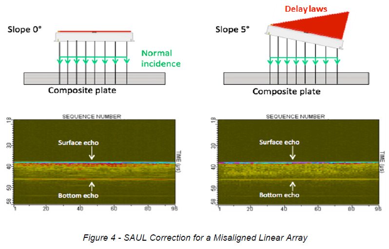
systems. Such systems work well, but do not address part-to-part variability. It is also common for systems to have features that allow repositioning of the part or adapting the scan plan where necessary. This, however, requires time and actions that must be performed in the tank, leading to an increased cycle time and loss of availability of the system to inspect parts. Figures 4 and 6 show the results of experiments performed to demonstrate SAUL’s ability to correct for probe misalignment. The top figures in Figure 4 show the position of a linear probe for two measurements, as well as the delay laws applied to the probe’s elements (indicated by the red bars). For the first measurement the probe was oriented parallel to the composite-plate test specimen and fired with no delay laws applied. The resulting B-scan is shown in the lowerleft image. For the second measurement, the probe was tilted 5 degrees from normal as indicated in the top-right image. In this case, SAUL was activated to calculate the delay laws required to compensate for the tilt of the probe. As described above, the objective of the SAUL
delay-law optimization is to generate a wave front that is normal to the front surface of the test specimen. The same principle is used for curved surfaces, where the incident wave fronts are optimized locally to match the surface (see Figures 5 and 6).
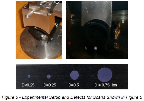
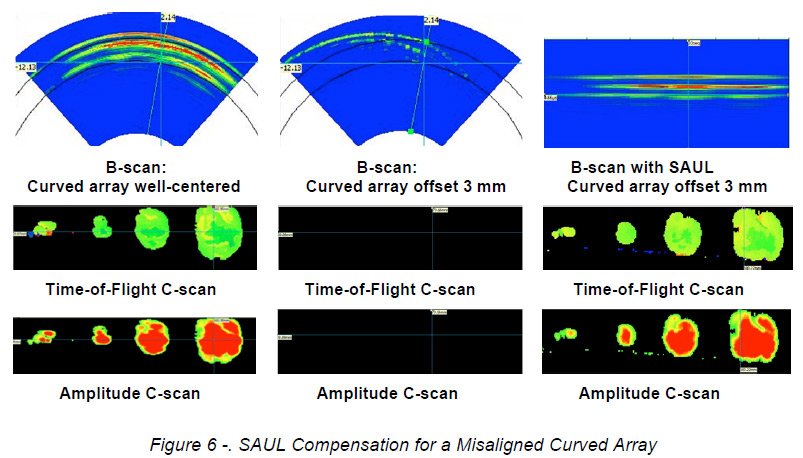
The experimental setup for measurements made with a curved array and a composite tube are shown in Figure 4 (top images), along with a picture of the release-film defects that were placed mid laminate in the tube (bottom image). The probe curvature is a good match to the tube, and all four defects were detected and imaged when the curved array was well centered on the test specimen as shown in the first column of Figure 5. When the probe was shifted 3 mm off center, all return signals were lost as shown in the center column. Maintaining the probe in the offset position and activating SAUL completely restores the signals as shown in the third column. Comparing the images in the first and third columns shows that the scans obtained with SAUL for the probe in the offset position agree very well with the images obtained when the probe was correctly centered on the test specimen.
The results of laboratory experiments and modeling were used to optimize SAUL for the wide design and optimization of the 4×16 matrix probe shown in the lower-left corner of Figure 3. This probe is being used to inspect hundreds of different composite parts in the first fully automated SAUL implementation at the EADS composites production facility in Aquitaine, France. The advantage of the 2D array is that geometry compensation is performed in two directions,
allowing the probe to be used on a variety of complex parts including those with small radii. The probe also successfully compensates for part variability, greatly improving productivity compared to installations using multiple probes and/or manual part manipulation.
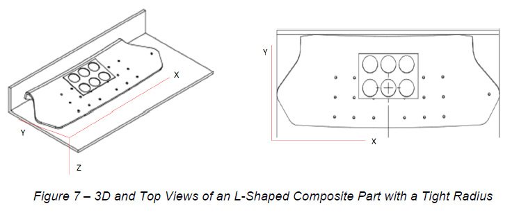
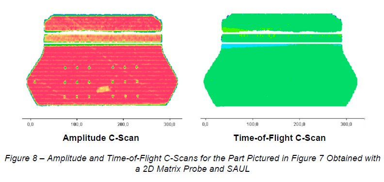
Figure 7 shows two views of a part inspected using SAUL with the 2D matrix probe described in Figure 3. The part is a composite L-shaped panel with a tight radius, most easily seen in the 3D image (left-hand picture). Although not easy to see in the figure, the part is curved in the X-Y plane. Amplitude and time-of-flight C-scans obtained for the part are displayed in Figure 8. For ease of interpretation, the C-scan images have been separated into three sections: the top
section corresponds to the vertical wall (short leg of the “Lâ€), the middle section corresponds to the radius, and the bottom section corresponds to the large panel region. Without SAUL, it was difficult to obtain acceptable results for the radius section. With SAUL, full coverage of the radius is achieved as can be seen in the C-scans.
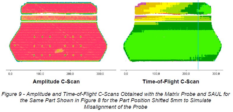
To simulate probe misalignment arising from part variability or poor positioning, the part was shifted by 5 mm in the long direction (X axis) and re-inspected with the probe position and scan plan unchanged. The shift in position results in the probe being at the wrong angle with respect to the part because of the curvature in the X-Y plane. This is evident in the time-of-flight (TOF) C-scan (right-hand image in Figure 9), particularly for the vertical wall and radius sections. The
non-uniform time of flight data indicates that the relative position of the probe and part has changed and is different from the scan plan (compare to the TOF C-scan shown in Figure 8 obtained with the probe correctly aligned). In spite of the misalignment of the probe, the amplitude C-scan obtained using SAUL (left-hand image in Figure 9) compares very well to the C-scan obtained with the probe correctly positioned (left-hand image in Figure 8). The agreement of the two amplitude scans demonstrates that SAUL has successfully compensated for the misaligned probe.
Conclusions
Advanced technologies don’t necessarily equate to a state-of-the-art system. Integration is the key. Not only must the NDT solution be capable of meeting the inspection challenges, but the integrated system must also be able to meet the production requirements. Quality must be ensured while also maintaining high production volumes. CAD/CANDT reduces the entire manufacturing cycle time, as NDT and CAD personnel become part of a unified team. SAUL has the ability to compensate for misalignment and part variability, and is therefore an important tool in achieving system compliance in the face of industrial realities. A fully integrated CAD/CANNDT system with SAUL is an industrial solution that has been demonstrated to be capable of meeting today’s demanding challenges of composite manufacturing.