
Please note: this paper is available for download on our PDF downloads page as well.
D. L. Hopkins1, M. Brassard2, G. A. Neau1,4, Jean-Noel Noiret3, W. V. Johnson1 and L. Le Ber4
1BERCLI Corp., Berkeley, CA 94703
2Contour Dynamics Inspection Systems, Levis, Québec, G6V 7M5, Canada
3EADS Composites Aquitaine, Salaunes, 33160, France
4M2M, Les Ulis, 91940, France
Abstract. Results from laboratory experiments and a fully automated industrial implementation are presented to demonstrate the ability of Surface-Adaptive Ultrasound (SAUL) to mitigate the challenges of complex geometry, variability of parts, and misaligned probes, while decreasing inspection times and costs. Shape-corrected scans are presented for a variety of parts demonstrating SAUL’s ability to adapt the incident wave to the geometry, even for tight radii measured with a linear probe. Results for a linear and a curved array demonstrate that SAUL can compensate for misaligned probes.
Keywords: Ultrasonic Phased Array, Surface Adaptive Ultrasound, Self Adaptive, Shape Corrected B-scan, C-scan, Curved Array, Matrix Probe, Complex Composites, Tube, Stringer, Stiffener
PACS: 43.35.Vb, 43.35.Zc, 43.38.Hz, 43.60Fg, 43.60Lq, 43.60Mn
Introduction
Rapidly expanding use of composite materials is driving a need for versatile inspection solutions suitable for high-volume industrial applications. Surface-Adaptive ULtrasound (SAUL) was developed to help overcome several challenges associated with inspection of composite parts including: complex geometry and highly contoured surfaces, tight radii, ply dropoff and lap joints, non-parallel front and back walls, and part-to-part variability that is typically greater than is found with metal components. As described below, the surface-adaptive technique is applied on the fly and does not generally increase inspection times compared to electronic scanning. The data presented here include results from laboratory experiments on representative parts, as well as results from the first industrial implementation of SAUL at Contour Dynamics where the technique is being used to inspect a wide variety of composite aerospace components. For this fully automated implementation, an average inspection time of 2.5 minutes has been achieved using SAUL for a variety of small parts, which is substantially faster than the required speed of 4 minutes per part. The use of SAUL has also made it possible to use the same matrix probe for parts with complex geometry and for a wide variety of parts.

Figure 1. For the SAUL surface-adaptive technique, the specimen shape is measured from the front-surface echoes obtained by firing all elements of the array without focusing as indicated in the left-hand image for a linear probe. An iterative process is then used to calculate time delays in real time that are optimized to create an incident wave that is optimally adapted to the surface geometry (right-hand image).
Surface Adaptive Ultrasound (SAUL)
Surface-Adaptive ULtrasound (SAUL) is a patented technique
[1,2] that has been implemented by M2M as an option on their fully parallel MulitX phased-array systems. Because the technique is applied in real time, it is well suited to automated inspections in high-volume production environments. When applied, the elements of the probe are fired in transmission without focusing and the specimen shape is measured from the front-surface echoes. An iterative process is then used to adapt the signals to the geometry to obtain shape-corrected scans on the fly [3-4]. The procedure is illustrated in Fig. 1 for a linear array. For the initial measurement that provides the shape information, the signals are generated without any time delays applied to the probe’s elements, as shown in the left-hand image in Fig. 1. The iterative process then calculates time delays adapted to the geometry to create an incident wave that is normal to the surface (right-hand image).
B-scans obtained with and without SAUL for a variety of curved composite parts are shown in Fig. 2. The scans were obtained with either a 5-MHz linear probe or a 5-MHz curved array. The part in the first row is a composite fork fabricated by the Trek Bicycle Corp. This part is challenging to inspect because of the tight radius and a change in geometry with length. Even with the tight radius, excellent results were achieved using a linear array with SAUL, as also demonstrated in earlier work [5-6]. Results obtained with a linear array on a hat-section stiffener show that the signals are well adapted to the radius, but the back-wall signals are relatively weak (row 2). The results in the third row were obtained with the curved array to inspect a hollow-core specimen. In this case, the curved array is not a perfect match to the part and without SAUL signals are only obtained over a relatively small area. Activating SAUL greatly improves coverage as evidenced by a much larger area over which a back-wall echo was obtained.
The difference in results between a curved array and linear array, with and without SAUL, can be seen by comparing the results in the last two rows in Fig. 2. The curved probe is a very good match to the curvature of the tube and would be expected to produce very good results (row 5). As expected, the results with and without SAUL are both excellent. Again as would be expected, the B-scan obtained with the linear array without SAUL has less coverage than the curved array, with signals obtained only where the probe is roughly parallel to the part (row 4). For the same linear probe, activating SAUL results in a B-scan with substantially more coverage and excellent signal quality.

Figure 2. B-scans obtained without (center column) and with SAUL (right-hand column) for a variety of curved composite parts. The scans were made using either a 5-MHz linear array (rows 1, 2 and 4) or a 5-MHz curved array (rows 3 and 5), as shown in the photographs. The shape-corrected scans measured with SAUL demonstrate that the technique is able to adapt the incident wave to the geometry, even for tight radii measured with a linear probe.
B-scans together with amplitude C-scans are shown in Fig. 4 for a Trek composite tube inspected with a 5-MHz linear probe without and with SAUL. Five release-film defects were embedded in the tube in the middle of the laminate as shown in Fig. 3, except in this case two of the large defects were included. Without SAUL, the two smallest defects were not detected. Activating SAUL allowed the two smallest defects to be detected and imaged (Fig. 4). The next section includes measurements made with a rectangular matrix probe (Fig. 5), which is advantageous in that it allows for adaptation to the geometry in two directions.
The objective of the inspection station designed and built by Contour Dynamics is to integrate state-of-the-art technologies for automated part handling and inspection to allow rapid evaluation of small complex composite parts [7]. The requirements for the automated process include the ability to reach high production volumes for hundreds of different parts; the ability to provide 100% inspection at a rate of four minutes per part; and the ability to handle and inspect complex parts with significant variability. To meet these requirements, the inspection station integrates a vision system with robotics and an M2M phased-array system equipped with SAUL. The inspection station is installed at EADS Composites Aquitaine, and is currently being used to evaluate an aerospace ship set of stringers and stiffeners made from Carbon-Fiber-Reinforced Plastics (CFRPs), which are typically anisotropic and attenuative. The set consists of 250 different parts that are relatively small, with dimensions on the order of 700 x 200 x 200 mm. The parts are also thin (1-9 mm), and many have tight radii, both convex and concave, with a radius of curvature that varies between 4 and 7 mm. The defects of interest are delaminations and in-plane porosity. Parts with delaminations greater than 6 mm in diameter or porosity greater than 2% are rejected.

Figure 3. Size of release-film defects placed mid laminate in composite tubes inspected with linear and curved probes with and without SAUL. The results are shown in Figures 2, 4 and 9. Note that the smallest defects were cut by hand, resulting in significant variability in size.
Additional inspection challenges include the variance between delivered parts and CAD drawings, relatively high part-to-part variation, and surface irregularities such as ply dropoff and variations arising from the curing process. The complex geometries and part variability make accurate automated part following difficult, and the rapid inspection rates required can make it unrealistic to use multiple probes and/or complicated scan paths.

Figure 4. B- and C-scans obtained without and with SAUL for the composite tube shown in the upper-right photograph. When the surface-adaptive SAUL algorithm was not used, the smallest two defects were not detected in the C-scan (middle row). Activating the SAUL algorithm improved coverage as can be seen by comparing the B-scans in the top row, and allowed all of the defects to be detected and imaged in the C-scan (bottom row).
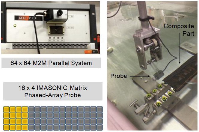
Figure 5. Inspection station at EADS Composites Aquitaine designed by Contour Dynamics to automatically handle 250 different composite parts. The parts are inspected using an IMASONIC 16×4 matrix probe (lower-left image) used in conjunction with an M2M 64×64 fully parallel phased-array controller equipped with SAUL (upper-left photograph). The light-colored elements in the schematic drawing of the probe indicate that groups of 16 elements are active at a time. A five-axis Cartesian robot positions the probe, which is shown in the right-hand photograph along with a composite part.
Because of these challenges and the requirements for speed and versatility, the inspection strategy adopted is to use a 16×4 IMASONIC matrix probe and an M2M phased-array system equipped with SAUL. The matrix probe, designed and optimized using CIVA software, was chosen to allow for compensation of geometry in two directions. A five-axis Cartesian robot holds the probe (Fig. 5). As also indicated in Fig. 5, 16 elements of the probe are active for each measurement. The active elements are then electronically translated across the probe.
The top image in Fig. 6 shows a composite test specimen created by Contour Dynamics for experiments designed to test SAUL’s ability to improve results for curved composite parts. The part has three sections: a relatively flat horizontal section, a radius, and a vertical section. The two C-scans in Fig. 6 are for the horizontal section of the test specimen. Seven through holes were drilled into the part as indicated in the top image, along with four flat-bottom holes drilled from the opposite side. The lower-left image is a conventional C-scan of the horizontal section, and the lower-right image is the C-scan obtained for the same part using the matrix probe and SAUL. All of the holes are clearly imaged in both scans.
C-scans without and with SAUL for the radius and vertical section are shown in Fig. 7 for two different areas of the part. The top images in the figure show the conventional C-scans. The results obtained for the radius are insufficient and do not allow identification of embedded defects. Using the same matrix probe with SAUL activated produced the results shown in the lower images. The results for the vertical section compare well with the conventional C-scan, and the results for the radius are greatly improved. With SAUL, artificial defects embedded in the radius were detected and imaged.

Figure 6. The top figure shows a composite test specimen created by Contour Dynamics for experiments designed to test SAUL’s ability to improve results for curved parts. As shown in the schematic diagram on the upper-right-hand side, the part has three sections: a relatively flat horizontal section, a radius, and a vertical section. Seven through holes were drilled into the part as indicated in the top image, along with four flat-bottom holes drilled from the opposite side. The lower-left image is a conventional C-scan of the horizontal section. The lower-right image is the C-scan obtained for the same part using the matrix probe and SAUL.
Results are presented below from two experiments designed to study SAUL’s ability to correct for probe misalignment. The results shown in Fig. 8 are for the same horizontal panel pictured in Fig. 6. In this case, measurements were made with the same matrix probe with SAUL activated for the probe optimally positioned parallel to the surface of the part, and then with the probe tilted 5° with respect to the surface (see diagrams in Fig. 8). The bottom-left image in Fig. 8 shows the time delays applied to the probe’s elements to compensate for the misalignment. The resulting C-scan images are very comparable, and all of the holes are clearly visible in the scan with the probe tilted.

Figure 7. Images obtained for two regions of the vertical and radius sections for conventional C-scans (top images) and the matrix phased-array used in conjunction with SAUL (lower images). For the conventional C-scans, the radius images are insufficient for defect detection and imaging. The radius images are greatly improved using the matrix array with SAUL, allowing artificial defects embedded in the radius to be imaged.
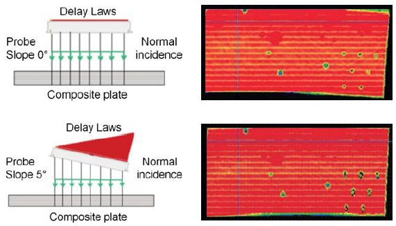
Figure 8. Results of experiments performed at Contour Dynamics to determine the ability of SAUL to correct for probe misalignment. The top-right C-scan image was obtained using SAUL with the phased-array probe correctly positioned parallel to the part (as indicated in the top-left diagram). The bottom-right C-scan was obtained using SAUL with the probe tilted 5° as indicated in the bottom-left diagram. The diagram also shows the time delays (delay laws) applied to the elements to compensate for the probe tilt.
A second set of experiments was performed on the same composite tube used to obtain the results presented in Fig. 4. For the images shown here, the measurements were performed with the 5-MHz curved array that is a very good match to the curvature of the tube, as shown in the bottom-left photograph in Fig. 2. The measurements were made with and without SAUL, for the probe well centered on the part and then progressively shifted off center in 1-mm increments. The images on the right-hand side of the figure are those obtained without SAUL. Even for a 1-mm offset, there is substantial degradation in the images, and the signals are completely lost for a 2-mm offset. In contrast, for the same measurements with SAUL activated, the defects are still clearly imaged with an offset of 3 mm (images on the left-hand side).

Figure 9. Comparison of measurements with and without SAUL for a curved probe used to inspect the composite tube shown previously (left-bottom photograph in Fig. 2). Without SAUL, the signals quickly degrade when the probe is shifted off center (right-hand images). In contrast, activating SAUL allows the release-film defects to be imaged with an offset as great as 3 mm with relatively little signal degradation.
Conclusions and work in progress
The results presented here for both laboratory experiments and a fully automated industrial application demonstrate that the SAUL technique is able to adapt incident waves to complex geometries and is a viable solution for overcoming several of the inspection challenges presented by composite parts. Release-film defects as small as 3.5 mm have been imaged in radii less than 7 mm using SAUL with a linear probe. Results using both a linear and a curved array demonstrate SAUL’s ability to compensate for probe misalignment. For the curved probe, results show that even when misalignment results in complete loss of signal, excellent results can still be achieved using SAUL. Decreasing the sensitivity to probe alignment greatly eases the challenge of mechanical scanning and robot tracking, thereby reducing mechanical complexity and costs.
For the Contour Dynamics system installed at EADS, SAUL provides a solution for inspection of a tight radius that could not be adequately evaluated from a conventional C-scan. A curved array optimized for the radius is an alternative solution, but would add cost, complexity and inspection time. In addition, accurate positioning is essential for curved arrays, and is challenging because of the part-to-part variation that is typical for composites. SAUL was chosen as the best option because it operates in real time and offers tremendous versatility, allowing the same probe and inspection strategy to be used for complex shapes and a wide variety of parts. Using SAUL, the average inspection rate for the various part geometries in the ship set is about 80 mm/sec, corresponding to a typical inspection time of 2.5 minutes. This is substantially less than the required inspection speed of 4 minutes per part. These results demonstrate that SAUL offers a cost-effective solution for complex geometries, while also addressing the variability in parts and probe alignment that are typically encountered in production environments.
Work in progress is focused on stabilization of SAUL for the wide variety of geometries and conditions encountered in industry. This includes improving signal-amplitude consistency to ensure accurate and repeatable sizing capability. Testing is also underway of an automated version of SAUL that has been developed to minimize the user input required.
References
- S. Robert, O. Casula and E. Iakovleva, French Patent No. FR 11/60399 (Nov. 2011).
- S. Robert, O. Casula and A. Nadim, French Patent No. FR 10/56217 (July 2010).
- N. Dominguez and G. Ithurralde, Ultra-Fast Ultrasonic Inspection for Aeronautical Composites Using Paintbrush Acquisitions and Data Processing on GPU, In Proc. European Conference on NDT, Moscow, 2010.
- S. Robert, O. Casula, M. Njiki and O. Roy, Assessment of Real-Time Techniques for Ultrasonic Nondestructive Testing, Review of Progress in QNDE, in press, 2012.
- D. L. Hopkins, G. A. Neau, W. V. Johnson and L. Le Ber Surface-Adaptive Ultrasound for Phased-Array Inspection of Complex Composite Specimens, BERCLI Corp., 2012.
- D. Hopkins, G. Neau and L. Le Ber, Advanced Phased-Array Technologies for Ultrasonic Inspection of Complex Composite Parts, in Proc. Smart Materials, Structures, & NDT in Aerospace, NDT in Canada 2011, 2-4 Nov., Montreal, Quebéc.
- M. Brassard, E. Pelletier, D. Hopkins, G. Neau and S. Robert, Self-Adaptive Robotic Phased Array Inspection System for Small Composite Parts of Various Geometries, In Proc. ASNT NDE of Aerospace Materials & Structures III, St. Louis, MO, 4-5 June 2012.