CAD2UT is an automated off-line planning software for pulse-echo inspections of simple and complex parts. It uses the part curvature information to automatically create UT inspection paths that cover the whole part surface with the minimum scan passes. This is done by flattening the original 3D geometry before applying a 2D raster scan and to rebuild the 3D scan path by applying an inverse transformation. This leads to simpler motion adapted to UT raster scans and allows the use of mid-range ultrasonic instruments equipped with 2 encoder input.
This software specifically designed for UT replaces teach pendant as a means to generate trajectories. The process starts with a STEP file of the component surface to create a triangle mesh of the surface. CAD2UT generates an inspection path as a raster scan using curvature information to adjust dynamically the indexation between two passes. Four path generation methods have been developed and implemented to fit most geometries inspected by ultrasonic. The path is directly exported to a robot simulation software such as ROBODK and then exported as a scan plan for robots or cartesian machines.
The process step are as follows:
1- 3D STEP FILE Import
2- Surface Meshing
3- Flattening
4- Path Generation
5- G or Robot codes
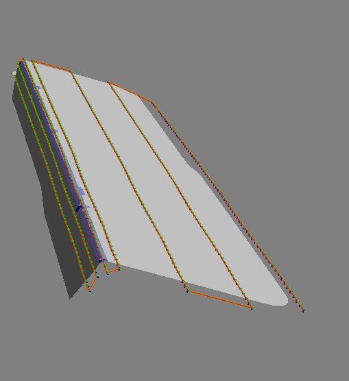
The first step is to import the 3D CAD surface. For UT, only the surface is required. The file goes through a couple of processing steps to transform the surface into an easily usable triangle mesh. This is transparent to the user.
CAD software can export surfaces as triangle meshes but these meshes are typically not appropriate for UT scan plans. The CAD2UTScans software performs this task by stitching adjacent surfaces to produce triangles sizes appropriate for scanning. The operator can also adjust the maximum and minimum triangle sizes when needed.
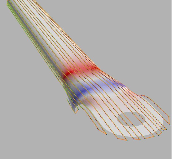
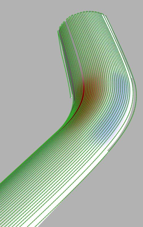
Part shown has a small radius (5 mm) that requires smaller meshing in this region. Larger meshes are used for the flat and the wall.
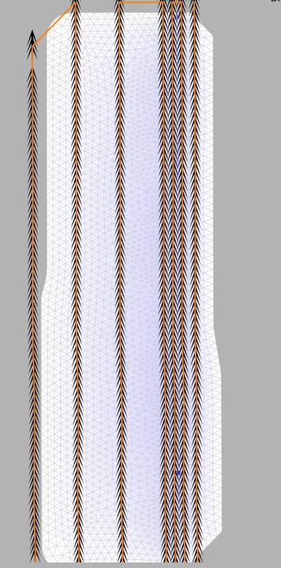
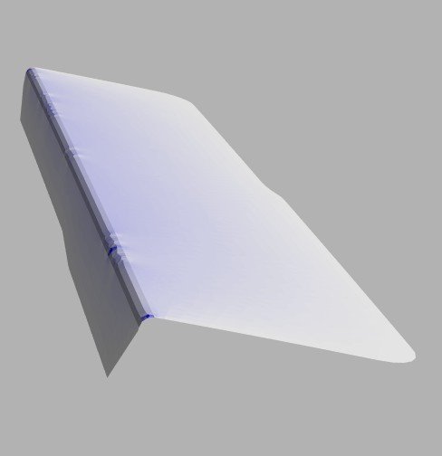

Flattening is a mapping from a 3D-embedded curved surface to a plane. This is done to automate path creation in two directions and to convert 3D spaces into scan-index coordinates used by UT instrumentation. The flattening process allows going back forth between the 2D and 3D part representations. Scan an index directions are determined using principal component analysis.