Ultrasonic inspection of certain composite materials can be difficult. In fact, highly dense composite materials produce noisy ultrasonic response to pulse-echo inspections. Also, through transmission techniques cannot always be implemented due to mechanical restrictions and limitations. The use of a reflector plate
can be a valuable alternative.
A complex shape composite component was inspected for the reliable detection of Ф 3 mm delaminations. Various ultrasound parameter sets were tested on a part with artificial defects simulating delaminations of Ф 2, 4, 6 and 12 mm. Pulse-echo (PE) phased array ultrasound was used to have the flexibility to easily change the beam width and the focusing, hence providing a broad range of test configurations. Frequencies between 1 and 10 MHz were used.
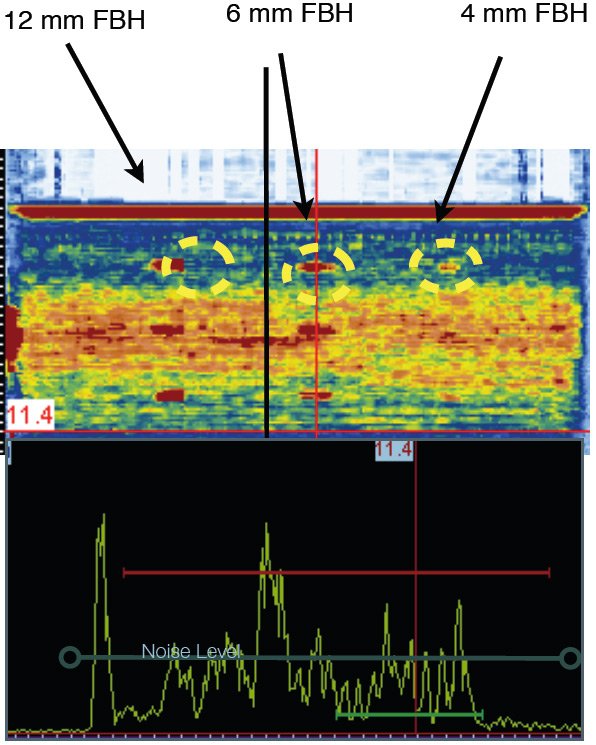
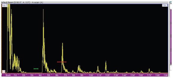
The best results obtained are shown in Figure 1. We observe that defects smaller than Ф 6 mm are difficult to detect. Considering the limitations of the PE technique and the fact that through-transmission (TT) could not be used because of mechanical interference and limitations, the reflector plate inspection method was used. This PE technique is commonly used for the inspection of flat plates and is also known as double through-transmission as the ultrasonic signals travels twice through the component.
 The PE reflector plate method consists in measuring the loss of amplitude of the return signal from the reflections off the plate with a polished surface. The distance between the component and the reflector must allow proper discrimination of the component back surface echo from the reflector echo.
To inspect the component, the transducer orientation is first adjusted to maximize the returning echo from the front surface of a stainless steel reflector plate.
Secondly, the water columns (transducer to component and component to reflector) are adjusted to ensure that the echo from the reflector remains within the narrow temporal gate.
In order to identify the reflector plate return signal, a plastic ruler is placed between the test part and the reflector. The reflector signal is automatically lost when the ruler blocks the ultrasonic beam between the component and the reflector.
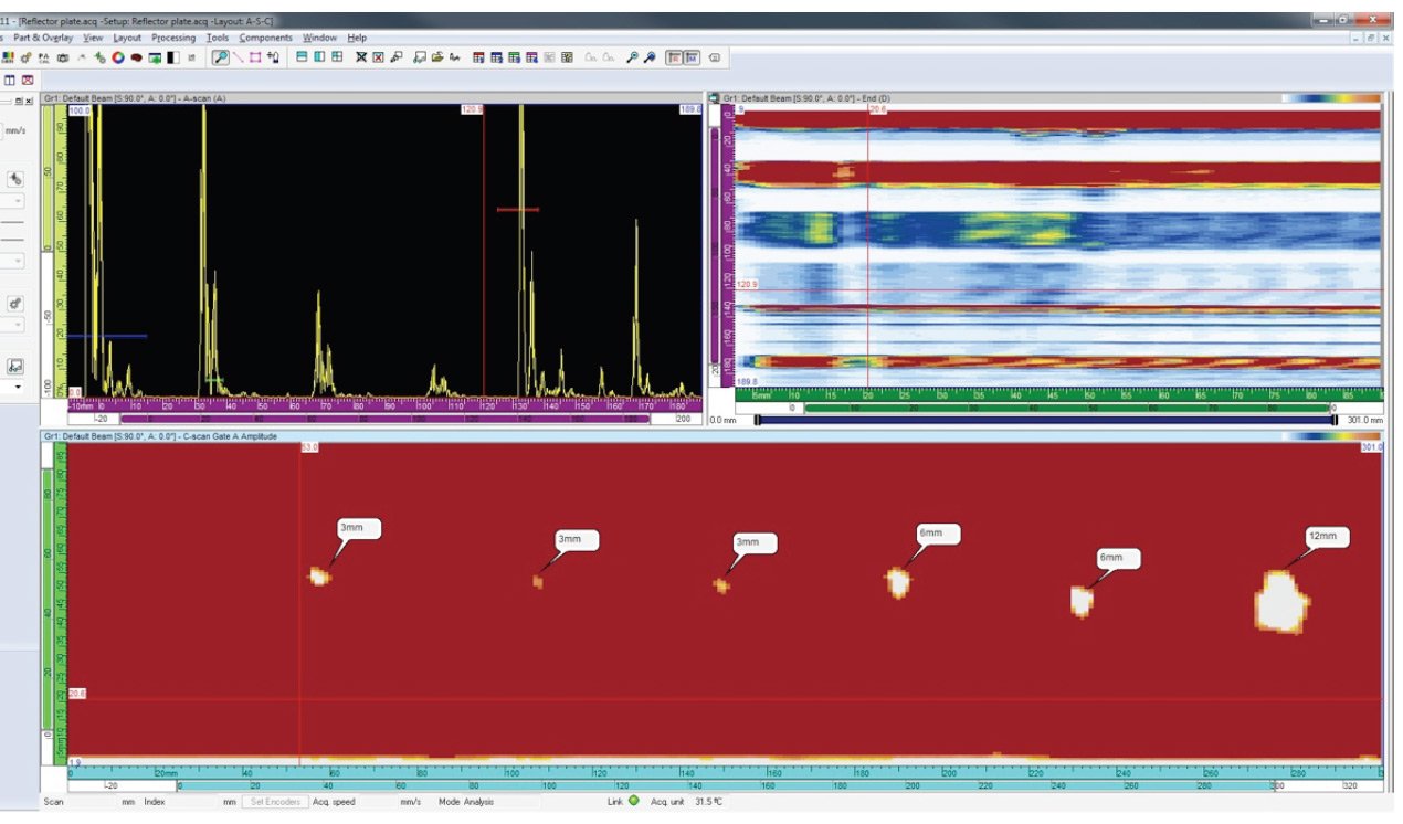
 Measurements were taken with this technique (see Figure 2) and were compared to the results from the PE technique (Figure 1). The noise reduction is significant. Also, the reflector plate echo is isolated in the gate (Figure 2).
 The adaptation of the reflector plate technique to this application requires the shaping of the reflector in order to match the profile of the component (Figure 4).
The transducer must follow the contour of the projection of the component on the reflector at a perpendicular angle. However, the reflector shape can be simplified as some deviations from perfect perpendicularity can be tolerated without significant impact on the results. In fact, the deviations will generate smooth changes in the amplitude signal whereas defect indications will show abrupt discontinuities.